Cetus ESP32 CPU upgrade
The first in a series of posts documenting my experience upgrading a Cetus MK3 3D printer with a TinyFab ESP32 CPU and BLTouch bed levelling probe.
So far I am very pleased with how this upgrade turned out. Both in terms of improved printing performance, as well as the increased flexibility of having a more open source system. I can now choose my slicer, modify/upgrade the firmware (Marlin) and add 3rd party hardware like the BLTouch. With these upgrades, hopefully there is plenty of life left in this little printer.
Since, at the time of writing, the ESP32 CPU is still beta and there is little in the way of documentation, I decided to document my notes and hope it may be of some help to anyone either thinking about or going ahead with their own upgrade. This isn't intended to be a step by step guide and assumes a working knowledge of 3D printers and electronics.
Additionally, I have posted details of my
My hardware
I have a stock Cetus 3D MK3 with extension board and heated bed.
My upgrade involved installing a TinyFab UP!/Cetus CPU ESP32 (beta) and a ANTCLABS BLTouch (Smart V3.1) auto bed levelling sensor. I cover installation of the BLTouch separately.
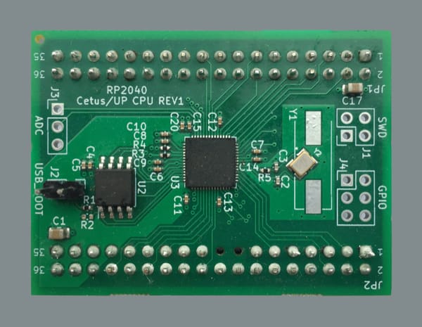
The TinyFab CPU is version/release V1/R2 (schematic). My board came with a couple of modifications:
- A black wire connecting EN on the ESP32 to VDD of U8 (a voltage supervisor IC)
- A red wire connecting P2, pin 11 to IO17 on the ESP32
Flashing firmware issues
I set out trying to flash the firmware via USB. However, the first issue I ran into is that the board wouldn't automatically enter serial bootloader mode.
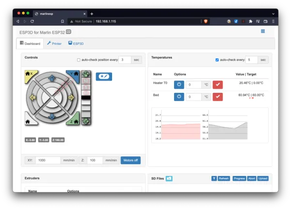
I considered trying an over-the-air (OTA) update but even though I am quite familiar with EP32s, I have to admit I have never used OTA updates. I was able to connect to the unit over WIFI (it defaults to an access point) but wasn't able to pull up a web interface and I didn't go any further.
The easiest solution to flash over USB seems to be to use a jumper/switch on the unpopulated header labelled P4 to pull IO0 low on boot.
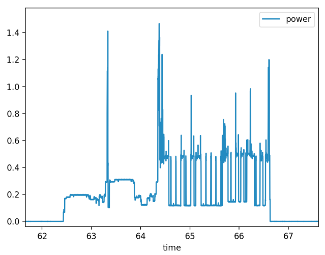
WARNING!My experience was that it was necessary to disconnect the cables to the hot end and heated bed, because all the heaters turned full on in bootloader mode. Not to mention the onboard speaker!
Ultimately I ended up performing the following modifications...
Hardware modifications
/BEGIN DISCLAIMER!
The following is my solution to the issues I described. I certainly may have missed something simpler and it's also possible that they've been resolved in future revisions of this board. It is possible that there may be unanticipated side effects from these changes (so far so good but I will update here if I discover any). In attempting to replicate what I've done, one could easily irreparably damage their board.
/END DISCLAIMER!
Basically, I found/made a spare output pin on the ESP32 and used in place of the voltage supervisor IC to disable much of the IO during boot. More specifically:
- I removed the black wire, which was essentially powering U8 (a voltage supervisor IC)
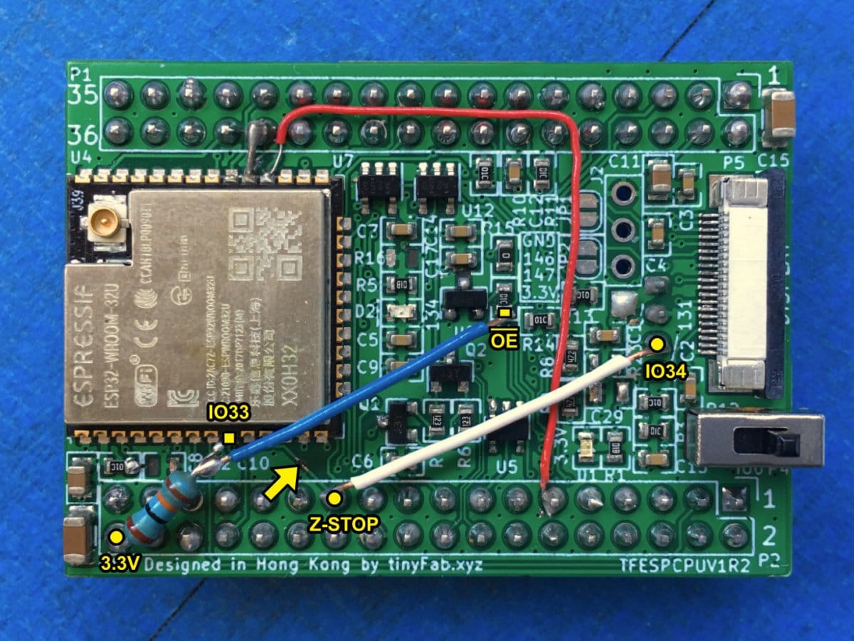
- I broke the track between IO33 on the ESP32 and header P2, pin 23 (Z-STOP)
- I soldered a pull up resistor (10k) from 3.3V to the IO33
- I soldered a wire from IO33 to OE
- I removed C29 and R23
- I connected IO34 to P2, pin 23 (Z-STOP)
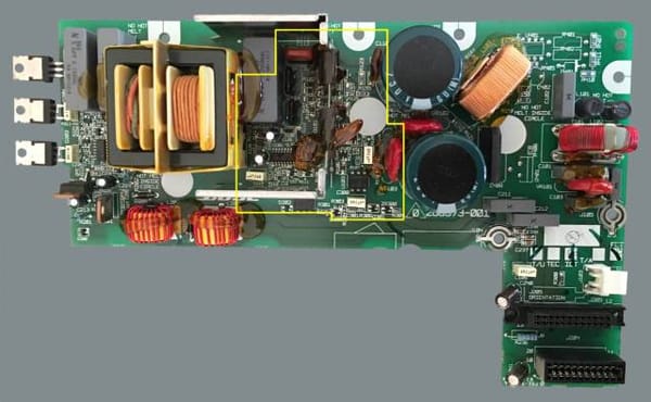
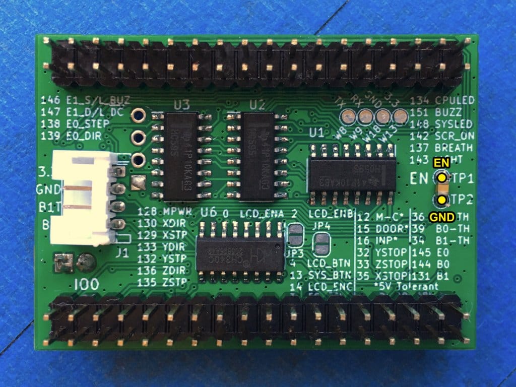
- I added a 1uF capacitor to EN (between TP1 and TP2 on the back of the board). This is a common issue/solution for boards using this kind of serial RTS, DTR reset circuitry. Effectively it delays EN going high on power/reset, which may be necessary to coax the ESP32 into serial bootloader mode, especially on Windows. Often a 10uF cap is recommended but 1uF worked for me.

Firmware modifications
In addition to the hardware modifications, in firmware it was necessary to:
- Free up IO33 by moving Z-STOP to IO34
- Define a PREINIT macro to pull OE low at the beginning of the Arduino setup() function.
In Marlin/src/pins/esp32/pins_MRR_ESPE.h:
#define BOARD_INFO_NAME      "MRR ESPE"
#define BOARD_WEBSITE_URL    "github.com/maplerainresearch/MRR_ESPE"
#define DEFAULT_MACHINE_NAME BOARD_INFO_NAME

#define BOARD_PREINIT() { \
  OUT_WRITE(33, LOW); \
}

//
// Limit Switches
//
#define X_STOP_PIN                            32
#define Y_STOP_PIN                            35
#define Z_STOP_PIN                            34
Discussion
Maybe a few words on my thought process here...
Firstly, the larger capacitor on the EN should have fixed the USB auto bootloader issue for me, except what appeared to happen was the ESP32 would hang (or got stuck in a boot loop, I didn't investigate thoroughly) with all the heaters on if not disconnected. I'm guessing the delay on EN from the capacitor may have prolonged the startup delay of the voltage supervisor IC. Whatever was going on, it just seemed to me using a dedicated output rather than the voltage supervisor to enable IO after boot had the advantages of 1. not relying on a potentially sensitive time delay, 2. in the event of a boot failure the heaters wouldn't turn on, and 3. in serial bootloader mode the heaters won't turn on.
The only problem is there are no spare IO on the ESP32. IO34 is connect to B-THERM2 and since I have a stock heated bed I figured it was expendable. There are also some LCD IO that I could have used but I thought that was a more likely upgrade for me. Since IO34 is an input only, I connected this to Z-STOP to free IO33.
Other firmware modifications
Swapping axes
I also swapped my X and Y axes and put home (0, 0) at the front left corner of my bed. This isn't necessary but seems to be a convention and makes working with Marlin and most slicers easier. These are the relevant settings in Marlin/Configuration.h:
#define USE_XMIN_PLUG
//#define USE_XMAX_PLUG

#define INVERT_Y_DIR false

#define X_HOME_DIR -1
And in Marlin/src/pins/esp32/pins_MRR_ESPE.h:
#define X_STOP_PIN                            32
#define Y_STOP_PIN                            35

#define X_STEP_PIN                           132
#define X_DIR_PIN                            133

#define Y_STEP_PIN                           129
#define Y_DIR_PIN                            130
Home offsets
To align the print area more closely with that of the stock machine and the centre of the bed, I added a 3mm offset in Marlin/Configuration.h (assuming X/Y configured as above):
#define X_MIN_POS -3
#define Y_MIN_POS -3
Resources
I forked Marlin on GitHub and created a branch for my modified TinyFab version: https://github.com/richcarni/MarlinCetus3D. The original TinyFab version is tagged tinyfab_original.