Cetus BLTouch upgrade

In addition to my TinyFab ESP32 CPU upgrade, I also installed a BLTouch bed levelling probe on my Cetus 3D MK3.
Installation
I used this design to mount the sensor. I suggest checking the nozzle to probe offsets - mine differed from those quoted by a couple of mm. Also be careful of how the X and Y axes have been defined.
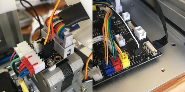
The BLTouch has two sets of connections, one for control (brown, red and orange wires) and one for sensing (white and black wires).
It seems the "typical" way to connect this up to a Cetus is to use the door check input for sensing and the unused header on the extruder board for control. I basically followed the super helpful write up at https://reeuwijk.net/post/162714620690/auto-bed-leveling-sensor-for-cetus3d https://www.tumblr.com/wbvreeuwijk/162714620690/auto-bed-leveling-sensor-for-cetus3d?source=share.
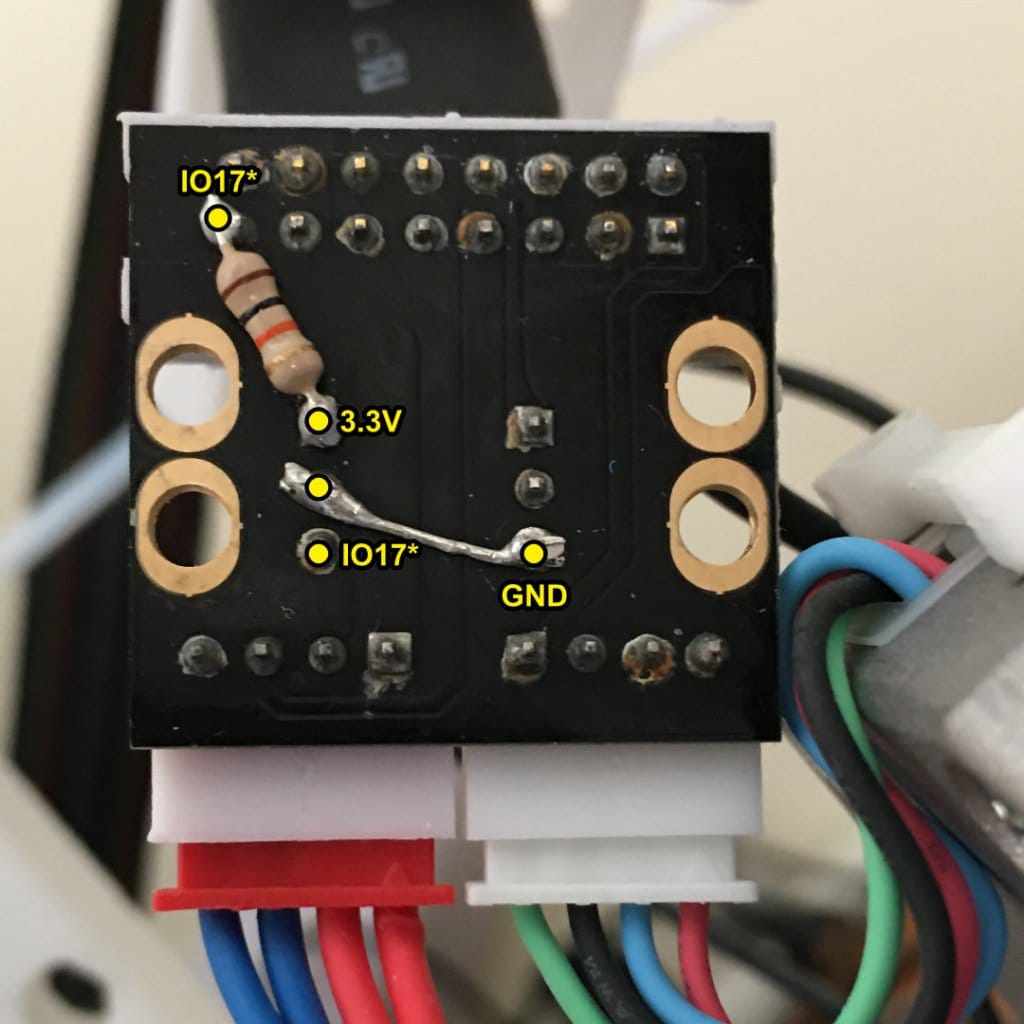
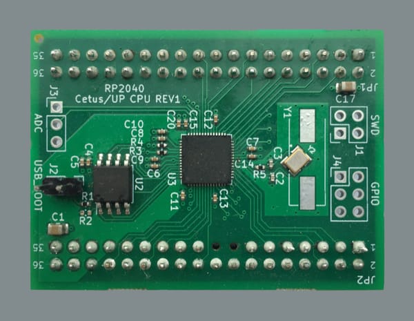
The problem with using the spare extruder header (IO17) is that the signal is inverted by a transistor on the Cetus mainboard (Q09 on my MK3). I couldn't figure out an equivalent to the SmoothieWare configuration solution documented here. I resorted to modifying the servo source code to invert the output. Ideally I'd prefer not make changes to "core" files like this.
In Marlin/src/HAL/ESP32/Servo.cpp:
void Servo::write(int inDegrees) {
  degrees = constrain(inDegrees, MIN_ANGLE, MAX_ANGLE);
  int us = map(degrees, MIN_ANGLE, MAX_ANGLE, MIN_PULSE_WIDTH, MAX_PULSE_WIDTH);
  int duty = map(us, 0, TAU_USEC, 0, MAX_COMPARE);
  duty = MAX_COMPARE - duty;
  ledcWrite(channel, duty);
}
I also considered some hardware solutions:
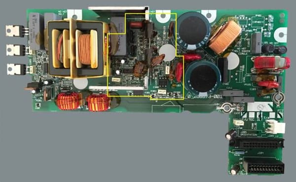
- Removing and bypassing transistor Q09. Relatively easy but would be somewhat difficult to reverse/undo. Seems like an odd excuse after all the modifications already made to the CPU board!
- Adding a simple inverting transistor circuit on the extruder board. Only tricky in that there isn't much spare space under the extruder cover.
Firmware - Pins
For me the pins were already setup correctly in firmware. For the setup just described they should be as follows.
In Marlin/src/pins/esp32/pins_MRR_ESPE.h:
// probe
#define Z_MIN_PROBE_PIN                       15
#define Z_PROBE_SERVO_NR                      0
#define SERVO0_PIN                            17
Calibration/Operation
There are many excellent online resources that cover the generic process of setting up and using a BLTouch. Some I found useful were:
- https://www.youtube.com/watch?v=eF060dBEnfs by Teaching Tech as a general overview
- https://www.youtube.com/watch?v=y_1Kg45APko&t=85s by Breaks'n'Makes for calibrating the Z-offset