Bose PS18 powered speaker repair
The unit wasn't powering up - no sound, no LED activity.
On opening up, the fuse had blown. On inspection, no visible signs of failed components.
I replaced the fuse and heard a pop and then the faint smell of magic smoke. In retrospect I should have used the series lightbulb method when testing to limit current - lesson learnt. The fuse didn't blow this time but I turned it off pretty quickly.
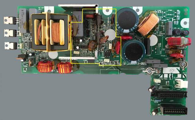
This time on inspection there was clear damage to U101 (L6598 resonant controller), C119 and Q102 (switching MOSFET) and a couple of its gate components.
Fortunately I was able to find a service manual, troubleshooting guide and full schematics for all the boards in this unit. Hopefully they are easy enough to find online:
- Lifestyle PS 18, 28 and 48 Digital Acoustimass Powered Speakers Service Manual
- PS18/28/35 Troubleshooting Guide
- bose-ps28-48-sd268573-schematics (PSU)
- bose-ps28-48-sd267086-schematics (DSP)
- bose-ps28-48-sd267083-schematics (Amp)
I did as much in-circuit testing as I could to identify any other adjacent components by proximity but couldn't find anything glaringly out of the ordinary. I also used backlighting to visually check trace integrity - was also useful for identifying interconnections.


Backlit (right) images around MOSFETs (Q101 and Q102) and controller IC (U101) post removal
So I replaced those components plus the complementary MOSFET and all the MOSFET gate components, in all:
- R101, R102, R103, R104
- C119
- D101, D102
- Q101, Q102
- U101
To do that I first removed the heatsink/shield. I used hot air to heat the shield, then wetted with leaded solder and used a solder sucker to desolder.
This time I tested with a series lightbulb. It flashed previously on power on and then turned off. No activity on the power/status LEDs. I tested the supply to U101 (pin 12), which should be 12 V, but instead read only 2.5 V.
I found some very helpful information on a forum: Repair SMPS power supply from Bose subwoofer. This was a huge help in narrowing down where to look - and as it turns out, the mode of failure there appears to be the same.
Round 2
Based on the experience from that forum post, I began removing components and testing in isolation. I ended up replacing the following, some because they had failed and others out of precaution, because it was just easier than testing them rigorously:
- Q103
- Q104
- U103
- D103*
- ZR101*
(*replaced but appeared to test OK)
And success! 11.5 V on pin 12. Connected up to the rest of the unit - amber LED on the DSP board lights up initially and then the green LED starts blinking slowly (indicating "smart" speaker off state)


Parts list
| Component | Description | Mfr. No. |
|---|---|---|
| R101, R103 | 10 ohm 1206 SMD 1/4W 1% | CRCW120610R0FKEAC |
| R102 | 33 ohm 1206 SMD 1/4W 1% | CRCW120633R0FKEAC |
| R104 | 100 ohm 1206 SMD 1/4W 1% | CRCW1206100RFKEAC |
| C119 | Polyester film capacitor 0.47uF 63volts 5% | B32529C474J |
| D101, D102, D103 | SOT-23-3 SMD diode | MMBD914LT1XT |
| ZR101 | SOT-23-3 SMD 12V Zener diode 300mW | BZX84C12LT1G |
| Q101, Q102 | TO-220-3 N-channel MOSFET | STFU10NK60Z |
| Q103 | SOT-23-3 N-channel MOSFET | T2N7002AK,LM |
| Q104 | SOT-23-3 PNP BJT | MMBT3906VL |
| U101 | High voltage resonant controller | L6598D |
| U103 | Optocoupler | CNY17F-1 |
List of the replacement parts used
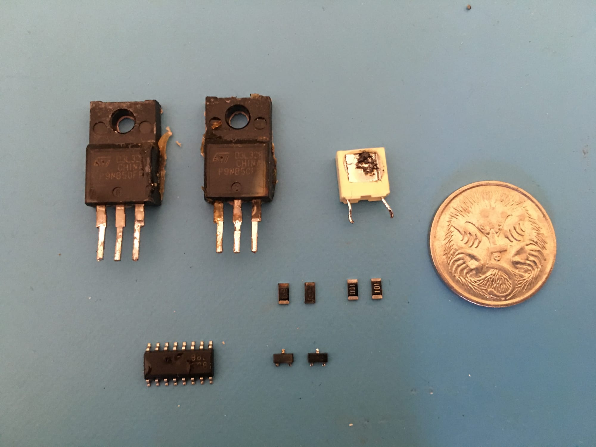
Q101, Q102 MOSFET selection
The specific power MOSFETs used in the PSU appear to be obsolete today and not readily available. It wasn't too hard to find a replacement (a couple of options shown below) with equivalent specs - except for maximum power dissipation in an insulated package. Hopefully the original design had some headroom in this respect.
| STP9NB50FP (original) | STP9NK50ZFP | STFU10NK60Z (replacement) | |
|---|---|---|---|
| P_tot (W) | 40 | 30 | 35 |
| ID (A) | 4.9 | 7.2 | 10 |
| RDS_on (ohm) | <0.85 | <0.85 | <0.75 |
| VDSS (V) | 500 | 500 | 600 |
| VGS_th (V) | 4 | 3.75 | 3.75 |
| dv/dt (V/ns) | 4.5 | 4.5 | 4.5 |
Power MOSFET comparison